Friday 26 February 2016

Eclipse Open IoT Challenge 2.0 - Final Update #10 : IOT VAIDYA IN ACTION! (Demo)

Welcome IOT VAIDYA! - an IOT doctor for you.The project is all set to check rural(as well as urban) patients and send their reports to a doctor who may be sitting in a totally different part of the world.We are finally finished with the project.Please take a look here.

What you will see in the video is the patient has sensors attached to his body and the program will start with the double click on the IOT VAIDYA launcher icon.A form opens up on this PiTFT 3.5'' Touchscreen and the basic information of the patient are filled.On clicking Submit, the diagnosis will begin.The audio from the speaker will guide the patient while diagnosis.Later on,after diagnosis, a "Success" message on the screen shows successful publishing of data.
The doctor in some other corner of the world(here, other corner of the room!) logs into his account on http://iotvaidya.mybluemix.net/ and sees ONE new patient has been added on the notification-bell.
He clicks on the patient's report and sees a page with all the data shown : Pulse, ECG, GSR and Temperature.Then he finds out the probable disease and intimates the same to the patient via SMS. He writes in a language in which he is comfortable but the message is received by the patient in his regional language.
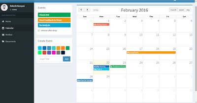
While this is the main functionality, we also have added calendar with drop-able events which doctor can write and drop on the desired dates to be considered as a reminder in future.

While most of the details of the project have been covered in the last two updates : #Update9 and #Update8 , this blog will highlight what we have not covered so far.

1. Installing PiTFT and bringing up X Windows Desktop:


Using PiTFT 3.5'' from Adafruit is very easy to use and install.We followed this easy install instruction.

Next, this link was quite helpful in getting things right with x windows desktop you see in the above picture.

2.Creating launcher: Using gnome panel.

sudo apt-get install --no-install-recommends gnome-panel

3.Patient form on the the display : Using python code and tkinter package.

sudo apt-get install python-tk


4.When we hit "Submit" in the form, the python code runs a system call to take "Name","Age","Contact" and "Village" as arguments and pass it to the the java application.

5.The sensors data does not look very accurate because we were still working on improving our algorithm to properly reconstruct the values.

6.The digital temperature sensor is quite accurate though.

Challenges were faced!

1.Sending image over MQTT was problematic due to the 4096B payload limit with IBM Bluemix IOTF service.It is interesting because it used to work few days back.Nevertheless we went ahead and used HTTP for the same.

2.Plotly for plotting Sensor data and using Mongo DB by Compose was causing the website to load slow.So we switched to Chartjs and MongoLab.

3.Finding translation API : Wanted something very easy to integrate in our project. https://mymemory.translated.net/ APIs were very easy and required just a single line of code.

4.What we really wanted was to add IBM Watson Q&A API for enhancing the capability of IOT VAIDYA and to make it some what cognitive.Sadly, the API is not open in trial period.We will keep on searching new methods to give it cognitive aspect.

5. Interfacing Analog sensors to Pi. As raspberry pi itself doesn't have analog pins, hence we were compelled to use external ADC. (MCP3008)

Amazing experience using open IoT standards:
1.Eclipse Kura:
Though Reactive Blocks allow the application to be built for various target platforms, it has got support for Kura too.
After using Kura for running applications on raspberry pi,these are the features which make it unique and impressive:
  • Run/Debug from eclipse
  • One Click Deployment
  • Web Based Console
  • Remote OSGI
2. Paho MQTT:
Implementation of Paho project into various languages make it plug and play.We used Java and python implementation of paho project in our application.

3.Github:
We have uploaded all the codes of our project in Github repository.iot_vaidya

4.Reactive Blocks:
Team reactive blocks is just awesome, they helped us a lot throughout this challenge. We have shared 60+ mails in last 45 days.

Response to project: 

It's been an amazing journey so far. We have got close to 1500 hits on our blog, 15+ followers on twitter, 50+ likes and 25+ retweets.
Especially tweets from Benjamin Kabe, Ian Skerett, Anne Nevein motivated a lot.

We would keep the project going, do keep supporting us.
Follow us on twitter:@iot_vaidya

Thursday 25 February 2016

Eclipse Open IoT Challenge 2.0 - Update #9 "Monitor your health with IoT Vaidya"

It's been an amazing week on the Tumblr, have seen some amazing projects so far.Through this post we would also like to throw some light on our work throughout this Open IoT challenge.

Our last post was about the cloud end of our project, this time it is about the Medical Gateway.


As we proposed in the beginning of competition for building a health monitoring system for patients in rural India, since then we have come a long way.

Components of the Medical Gateway:

Sensors which we are using in the medical gateway:
1.Heartbeat
2.Temperature
3.Galvanic Skin Response
4.ECG 

Along with the above sensors, we have also connected following accessories to make the device a full proof solution:

1.Camera: Camera is used for taking patient's relevant photos , which would be useful for doctor to diagnose the disease.

2.Speaker: As we are building this device keeping in mind patients of rural India , It's obvious that we keep it simple.As a result of this, all the instructions given to the patient while operating the device, would be in the form of audio in his/her regional language.

3.Keyboard:
It would be used to enter the primary information about the patient,
such as :
  • Name of the Patient
  • Age
  • Contact Number
  • Village

4. Display: For making the device more user friendly and convenient , we are using a Touch screen TFT display.


5.Power Bank:
To make the device portable, we are powering it using a 5V power bank.


Last But not the least :
6.Raspberry Pi(Heart and Brain of the Device)


How does the health monitoring system work:

1.Taking the Image and sending it to the Bluemix IOT service:

Note: As IBM Bluemix only allows maximum of 4096 bytes of MQTT packet size, it became complicated for us to send image using the MQTT. Hence we have used HTTP post request to send the image to cloud. 
Posting Image to IBM cloud

Application starts from the initial node

  1. The credentials of IBM Bluemix IOT device is passed using createParams operation. IoTFoundation block starts the IBM Bluemix session, using the credentials provided in the createParams , where all the sensor data would be send.
  2. Speech block converts the string into an audio.
  3. The Photo block captures the image and pass it to the Convert Image block where it is converted to JPEG.
  4. The makepost operation provide the URL for post .
  5. The HTTP Post block posts the image , after converting it to the json.It also gives the response. 

Once all the relevant images of the patient is send to the doctor, it is time to extract the data from bio sensors using ADC MCP3008 and deliever it to the IBM Bluemix Service using MQTT.
Here we have used Eclipse Paho project for MQTT.

2.Fetching all the data from bio sensors and sending it to Bluemix IOT service.

Note :Raspberry pi doesn't have its own ADC. For interfacing analog sensor ,you need to attach external ADC.We have used MCP3008.


Sending the sensor data to IBM cloud using MQTT
  1. Provide the credentials , to start a session with IBM Bluemix IoT cloud.
  2. "samprate" operation sets the sampling rate for ADC.
  3. The sensorBlock block gets the ADC values of all the sensors connected to various analog channels of MCP3008. The data from each sensor is recorded and stored in the form of array.This array is then converted to string.
  4. The string  is passed to Event block where it is converted to JSON and send to the registered IBM Bluemix cloud.
After building the project in eclipse ,we used kura to deploy it on the raspberry pi.Reactive blocks provide various target platforms such as Java source code, Java standard Edition, OSGI bundle project and Kura bundles.

To get the source code of our project , visit the Github repository.
Follow us on twitter too, to get constant updates.

Sunday 21 February 2016

Eclipse Open IoT Challenge 2.0 - Update #8 : IOT VAIDYA CLOUD - INSIDE OUT

This is probably one of the last updates on our project and will shed light on the iotvaidya – cloud in detail.So in this particular article we will try to explain what was done on the cloud side and how we wired up IBM Bluemix and other services with our project.

Okay! So let's begin.

Using IBM Bluemix is quite easy.It takes only few steps to get things up and running.I have explained in detail how to create an IOTF service and use it to subscribe to the events from any device  here.In the article I have shown how can we use the credentials on the “device” side to publish or subscribe to the events. If you want to use the IOTF service to subscibe or publish as an “application” hosted on IBM Bluemix, you will require API access key and Authentication token like the one shown below:


We will be using above access key and token(token will be generated along with API key ; it is one time and can be viewed only once.) in our node server code to “subscibe” to any event being published by the device( our raspberry pi gateway).
Once we are ready with the IOTF service with both kinds of credentials i.e, the one we'll use in our “device” and the one we'll use in our nodejs “application”, we'll navigate to the CATALOG tab and choose “SDK for Node.js”  


You will have to name your application and hit CREATE.


The nodejs application created! This application will be a very basic starter applcation and you can view it by hitting the route. The route is the URL of your application. In our case it is “iotvaidya.mybluemix.net”


Now, we don't want a simple starter application.We want to modify it according to our needs so we'll navigate to “Start Coding”. There are many ways to customize and manage your application like Eclipse, CF Command line interface and GIT. We will choose CF (Cloud Foundary) Command line interface.For this purpose you'll have to install CF Command Line Interface on your local machine.Follow the steps shown on the page.It is very easy.Then download the starter application, unzip it, modify it and simply push it using CF commands.It is all given on this page.

IOTVAIDYA NODE SERVER:

Now that we have the starter application directory with us.Let us modify the contents and include necessary codes and modules to build backend and front end of IOT VAIDYA CLOUD, backend first.We will remove everything from the directory except CHANGELOG.md,manifest.yml and package.json.
Create an app.js file.This is the main file in which we will write the logic and server code to manage our project.
Install following packages by using npm command “npm install package_name --save”

  • express
  • body-parser
  • fs
  • request
  • multer
  • mongoose
  • ibmiotf
  • path
  • sinch-auth
  • sinch-messaging
Include following lines in app.js after installing above packages.


Create host and port variables and assign them default and environment values as follows:


Listen on the assigned port.


This is pretty much what needs to be done for a basic server.Next, we'll add codes for giving features to our node server.Let's take IOTF service first.Remember the access key and token we were talking about, it will be used here to access IOTF service from IBM Bluemix.


Replace values in config variable according to the credentials you have. "Your device name" is the name of the device(Raspberry Pi) registered with IOTF service.Before writing the code to subscribe to the data, we will have to wire-up our server with mongodb database. We are using free database provided by Mongolab


Follow these steps to obtain the information required to connect to your MongoLab-hosted database(s):

  • Log in to the MongoLab management portal
  • Navigate to the MongoDB deployment that you wish to connect to
  • At the top of the screen, you will see a box with the connection information 


The first string is what you would use if you were to connect using the mongo shell and the second string which we'll be using is the standard connection URI string that MongoDB’s drivers and client libraries use.
Next, we create Schemas for doctor and patient data dSchema and pSchema respectively.Then we create doc model and patient model to save data. Now that we've connected our server with mongodb, time has come to subscribe to any data being published and to save it in our database.


The above code subscribes to the "payload"  being published by IOT VAIDYA gateway built on Raspberry Pi.The payload structure is as shown in images above.It hase "name","age","contact","village","temp","pulse","ecg" and "gsr". Apart from this, the payload also has another key : value  pair which is "photo". We are not saving photo in the mongodb but we are saving it on local directory located at "/public/dist/img/patient/profile/" (stores profile pictures of patients) and "/public/dist/img/patient/symptom/" (stores symptom pictures of patients)

The pictures subscribed are base64 encoded. So, we write a code to convert base64 string into image as shown in the code snippet.

We have subscribed and saved the patient information in our database and local directory.Now we will write code to handle Doctor Registration and Login. The Registration and Login pages are form type and use POST method.We will use app.post() method to handle information posted from these pages.

REGISTRATION:


Include above code in app.js. Multer adds a body object and a file or files object to the request object. The body object contains the values of the text fields of the form, the file or files object contains the files uploaded via the form. Basically we are using it to access individual data like name,email and password from registration page. The registration page posts the information to "/register"  route and this information is accessed through the request object "req". d is the doc model object and is used to save the textual information.Image is uploaded using upload() method from multer. More info on multer here.
The registration page looks like this:


LOGIN:

Similarly, we write code to handle login information.Authentication is being done by simple comparing email id and password pair with the one in the database.


The value YOUR_API_KEY  can be found on this page : https://mongolab.com/user?username=USER_NAME . After successful login, you will be redirected to '/entry?'+n where 'n' is the doctor's name you used to register.If the login is not successful, you will be redirected to the login page.
The log in page looks like this:


Okay, let's assume we have successfully logged into our account.The next page will show a table consisting of a list of patients from different regions.It looks as shown below :

This entry page may change in the next 2 days as we are working on including some extra feature to the website.

The patient data is retrieved from a jQuery Ajax call to the mongodb database as shown in the code snipped below.The response is parsed and traversed key by key to access each value. data_set is an array of arrays which stores rows of patient data. For drawing the table we have used jquery.dataTables.min.js. Following code snippet is written in entry.html inside <script></script> tags.


The html code for the table is as shown below:


NOTIFICATION-BELL:

Notice a small bell on the upper-right corner of the table page.The doctor will be notified whenever new patient will be added to the database.Currently it just shows number of new patients added since you last logged in.The logic is shown in following code snippet:


"test" is the collection name where patients are stored and "temp" is the collection where count of the patient is stored. If the count is greater in test than the value of "num" in temp, the notification div value is set to the difference of the two counts else, the bell shows "0".The internal ajax call uses PUT request to update the value of "num" in the temp collection.
The HTML code is as shown below:


PATIENT REPORT:

Once you click on "Report", you are taken to report.html page which shows you the detailed report of the patient which includes ECG,Heart Rate,Temperature and Galvanic Skin Response. 
We will not explain the entire HTML and javascript code here as it will make this already long post too long.We have used few charting plugins and themes for making the UI the way it looks.The entire project is put up on our github.The report page is populated from the data received by making jquery ajax calls to our database.


Okay, let's pretend that Rakesh is a real doctor, and he thinks that Rahul is suffering from maleria.He can send this message and the nesessary prescription using the text editor under FEEDBACK tab.

FEEDBACK :


HTML :


Note how the feedback is posted on /message route.The feedback is handled using following code snippet in our app.js file.


msg stores the message text and is included in the t_url string which requests the translation of the included message using GET.This translation API is free and is provided by mymemory.translated.net. Next, we send the translated message to the registered patient.Messaging API is provided by Sinch. The reason we are not using Twilio from IBM Bluemix is that it sends a default header message with every SMS.We get a key and a secret to use the API.
Usage : var auth = sinchAuth("key", "secret"); 

So our patient Rahul will receive a text messages like the one shown below:

Translation:"Rahul you may be suffering from Maleria"

MORE:
We are planning to add few more features to it to give it a final touch.These include Calendar and Google Maps.


To help doctors note down tasks to be done on a particular day


FINALLY:
After finishing the project development on local machine, we have to push it on IBM Bluemix using CF Command line interface.Type following command in your terminal:
cf push iotvaidya -c "node app.js"
Through this update we showed you the cloud and website part of our project in an almost detailed fashion.Update on the Gateway and sensors part will follow in few days.After that we will publish a demo video of our project.Entire project is put up on our github page.So you can check out all the codes that I talked about in this blog post.Stay connected for next few really amazing updates on IOT VAIDYA.Get new updates on Tumblr as well.Follow us on Twitter.


Sunday 14 February 2016

Eclipse Open IoT Challenge 2.0 - Update #7 : Now the doctor at distant knows your Heart Rate(bpm)

Whenever we visit a doctor , first and the foremost parameter which is recorded by the doctor is our heartbeat.As we are building a health monitoring device, it was very important that we include a heart rate sensor in our device too.

This post will guide you through the whole process:

Literature :
According to Wikipedia :
Heart rate is the speed of the heartbeat measured by the number of contractions of the heart per unit of time, typically beats per minute (bpm). The heart rate can vary according to the body's physical needs, including the need to absorb oxygen and excrete carbon dioxide. It is usually equal or close to the pulse measured at any peripheral point.

Why Heart Rate Sensor ?

Heart rate(pulse rate) is considered an important parameter for primary diagnosis due to following factors:
  • To see how well the heart is working. In an emergency situation, your pulse rate can help find out if the heart is pumping enough blood.
  • Help find the cause of symptoms, such as an irregular or rapid heartbeat (palpitations), dizziness, fainting, chest pain, or shortness of breath.
  • Check for blood flow after an injury or when a blood vessel may be blocked.
  • Check on medicines or diseases that cause a slow heart rate. Doctor may need to monitor patients pulse every day if the patient has a heart disease or if he/she is taking certain medicines that can slow the heart rate, such as digoxin or beta-blockers (such as atenolol or propranolol).
Principle of the sensor:

The heartbeat sensor is based on the principle of photo phlethysmography. It measures the change in volume of blood through any organ of the body which causes a change in the light intensity through that organ (a vascular region). In case of applications where heart pulse rate is to be monitored, the timing of the pulses is more important. The flow of blood volume is decided by the rate of heart pulses and since light is absorbed by blood, the signal pulses are equivalent to the heart beat pulses.

Descriptive diagram of Heart rate sensor


Working of Heart Rate sensor:

The basic heartbeat sensor consists of a light emitting diode and a detector like a light detecting resistor or a Photo diode. The heart beat pulses causes a variation in the flow of blood to different regions of the body.  When a tissue is illuminated with the light source, i.e. light emitted by the led, it reflects (a finger tissue) the light. Some of the light is absorbed by the blood and the transmitted or the reflected light is received by the light detector. The amount of light absorbed depends on the blood volume in that tissue. The detector output is in form of electrical signal and is proportional to the heart beat rate.

This signal is actually a DC signal relating to the tissues and the blood volume and the AC component synchronous with the heart beat and caused by pulsate changes in arterial blood volume is superimposed on the DC signal. Thus the major requirement is to isolate that AC component as it is of prime importance.
Schematic of the Hear Rate Module: Designed using EAGLE

Once the sensor is ready , we need to connect it to the Raspberry pi.

Note:Unlike beaglebone and Arduino , Raspberry Pi doesn't have any analog pins.Hence we need to connect an External ADC  such as MCP3008 to it.

Potentiometer is connected to Channel 0 of MCP3008, which is interfaced to Raspberry Pi 
MCP3008 is connected to Raspberry Pi using SPI protocol.
For Raspberry Pi B+ following is the pin configuration:
  • MCP3008 VDD -> 3.3V 
  • MCP3008 VREF -> 3.3V 
  • MCP3008 AGND -> GND 
  • MCP3008 CLK -> #14 (SCLK)
  • MCP3008 DOUT -> #13(MISO) 
  • MCP3008 DIN -> #12 (MOSI)
  • MCP3008 CS -> #10 (CE0)
  • MCP3008 DGND -> GND 
Once the hardware is ready , it's time to shift focus on the software.

On the software side we have a IBM IoT application that is developed with Reactive Blocks. The application runs on a Raspberry Pi with Eclipse Kura OSGi framework. Internet of Things (IoT) protocol MQTT is utilized to send data to IBM IoT foundation service.

In the IBM IoT application the heart rate data is sent continuously to the IBM Bluemix Foundation service via MQTT .

A brief description about the technologies used:

Kura:


Kura provides an OSGi-based container for IoT applications running in service gateways. By installing Kura on a device, not only can you turn it into a powerful IoT router that can be managed remotely, but you also have access to a complete application framework for deploying custom applications.
Learn more about Kura on the project’s website: http://www.eclipse.org/kura

MQTT:


Eclipse Paho is an open-source project that provides MQTT client implementations in many programming languages, and Kura is using Paho to provide high-level OSGi services for IoT communications between a gateway and the Internet.
Learn more about Paho on the project’s website: http://www.eclipse.org/paho

Reactive Blocks:


Reactive Blocks is an Eclipse plugin that helps developers create robust and flexible IoT applications block-by-block. This tool makes it straight-forward to express concurrency, an inherent property in IoT applications running on gateways which need to weave together streams of events.

For Kura, Reactive Blocks provides a special code generator, a library of building blocks for using Kura services and receiving configuration updates.

To explore more about Reactive Blocks and Kura follow these articles:
IBM IoT Foundation:


With the IBM Internet of Things Foundation you can collect event data from devices, forward it to other applications, and retrieve historical data.
For getting started with IBM IoT foundation , visit following link: IBM IoT Cloud

Finally , how the application was built:

For building the application which records ADC values and then sends it to IBM Foundation Cloud using MQTT , Reactive Blocks were used.


  1. Initialize the "IBM IoT Quickstart" block with a manual/random device id.
  2. Once the device is registered, the "IBM IoT Quickstart" Block generates a URI corresponding to it, which is then passed to "Open Browser" block which opens it in the browser(optional if you are running the application on Raspberry Pi)
  3. Set the Sampling rate for ADC
  4. The "GP2Y0A21YK0F" block fetches the data from ADC using MCP3008 block and passes it to the adcEvent operation.
  5. The adcEvent operation converts the double value into an event object, which is then send to the IBM IoT cloud by MQTT using IBM IoT Quickstart block.
Build and Deploy:

After building the application you need to upload it on the Raspberry Pi.

For building a kura based application , follow the link:http://reference.bitreactive.com/reference/develop-kura-app.html


Note:In addition to the application deployment package, you also need to deploy Reactive Blocks libraries and runtime bundles. This can be found in as a deployment package ReactiveBlocksLibraries.dp in the project target-definition-with-rb of your Package Explorer window.

Once the Kura application is successfully build,follow the instructions below:

  • Open the Kura's web console of your Raspberry Pi.
  • Choose Packages section on the left menu.
  • Install the two deployment packages: ReactiveBlocksLibraries.dp and HeartBeat.dpp
  • You might need to use the refresh button in order to see packages you installed.
Output on the Bluemix console:


Once the bundle is installed on the raspberry, output can be seen on the IBM Internet of Things Foundation Quickstart service .
Note: If you manually assigned a deviceid to your application , you need to enter it on the webpage.


Other Resources(You may find Useful):
In coming week we would be uploading more information about other sensors.

Wednesday 3 February 2016

Eclipse Open IoT Challenge 2.0 - Update #6 : First Look

Greetings fellow IoTians! We are ready with the first look of IoT Vaidya.We are progressing day by day and are very excited to show you the first version of IoT Vaidya's website.As is our aim, we want to bridge the gap between patients in rural areas and the doctors far away in the cities.The website is the field area of the doctors where they can view patients report,analyse it, send feedback or prescription and a lot more.While new features are being added to it, please take a look at IOT VAIDYA v1.0!

NOTE: The patients in the demo below are not real, neither are their diagnosis reports.This is just for the purpose of demonstration.The actual report will be published from our IoT Vaidya Diagnosis Hardware.

List of Patients

Notice a notification-bell to the upper-right corner.Doctor is notified whenever new patient is added or if any report is updated.

Patient's Report

The patient can send the pictures of cuts,burns,bites or any such thing which the doctor might want to see.


The current solution takes Temperature,Pulse-Rate,ECG and GSR as the parametes.Many more can be similarly added.

Feedback:SMS

The doctor can send the feedback/prescription on the patient's phone.He writes in the text editor shown above and it is sent in the form of SMS to the patient in the regional language.

Translation :"Vinod you are suffering from maleria"

As you can see, the SMS received above is in Hindi Language.Likewise it can be in any other language according to patient's region.

The website also works fine in the mobile view.Showing few snaps of the same.


Mobile View


That's it for now.The entire documentation will be posted soon as we come closer to the completion which will be very soon.The project will also be uploaded on github so stay in touch with IOT VAIDYA.You can also view our progress on tumblr here : http://openiotchallenge.tumblr.com/